Date: 28-9-2019
ARBS awards project excellence 2020
Project name : Lion milk & juices DC Refrigeration system description
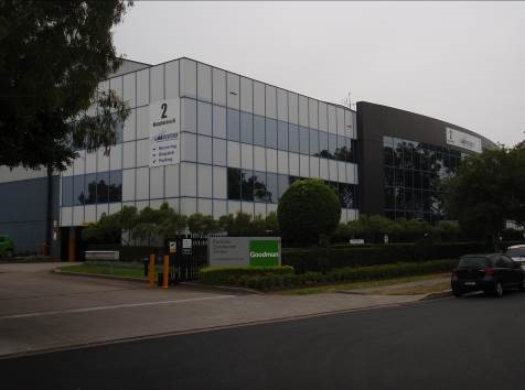
Site location : 1 Worth street Chullora
Executive summary
Lion milk and drinks division engaged Strathbrook Industrial Services to carry out a design and construct project, to install a refrigeration system in a large distribution centre that they were building in Western Sydney. Lion have some basic design concepts such as a preferred refrigerant and the use of Glycol as a heat transfer medium to reduce refrigerant charge which were to be the cornerstone of any future design.
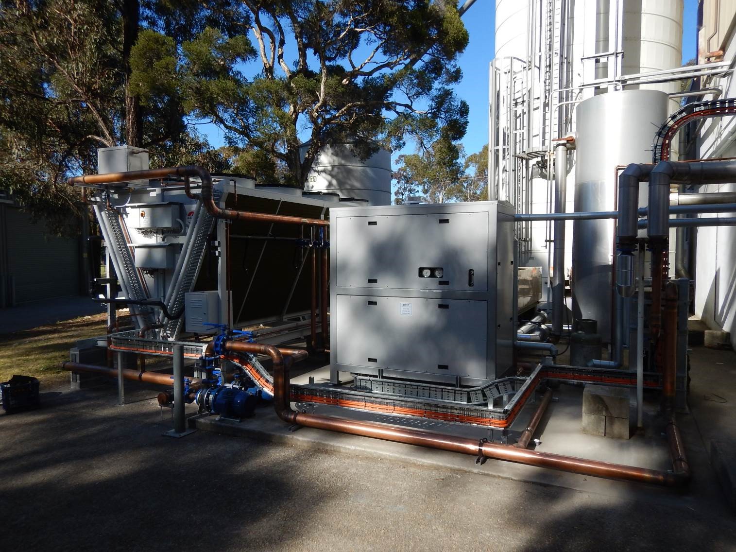
The cooling system that was installed employ’s three Mycom Ammonia screw compressor packages, each with a dedicated critically charged, flooded ammonia evaporator and surge drum. Each package is close coupled to a dedicated evaporative water-cooling tower located on the plant room mezzanine deck above the compressors sets.
Each package operates independently and cools food grade polypropylene glycol which will be circulated around the site to affect the cooling.
Two 16000 litres insulated 316 grade stainless steel tanks act as supply and return tanks for the chilled glycol so that pumps can circulate the glycol as required, and the additional volume provided by the tanks provides thermal storage and allow the glycol pumps to maintain a positive suction head to prevent pump cavitation.
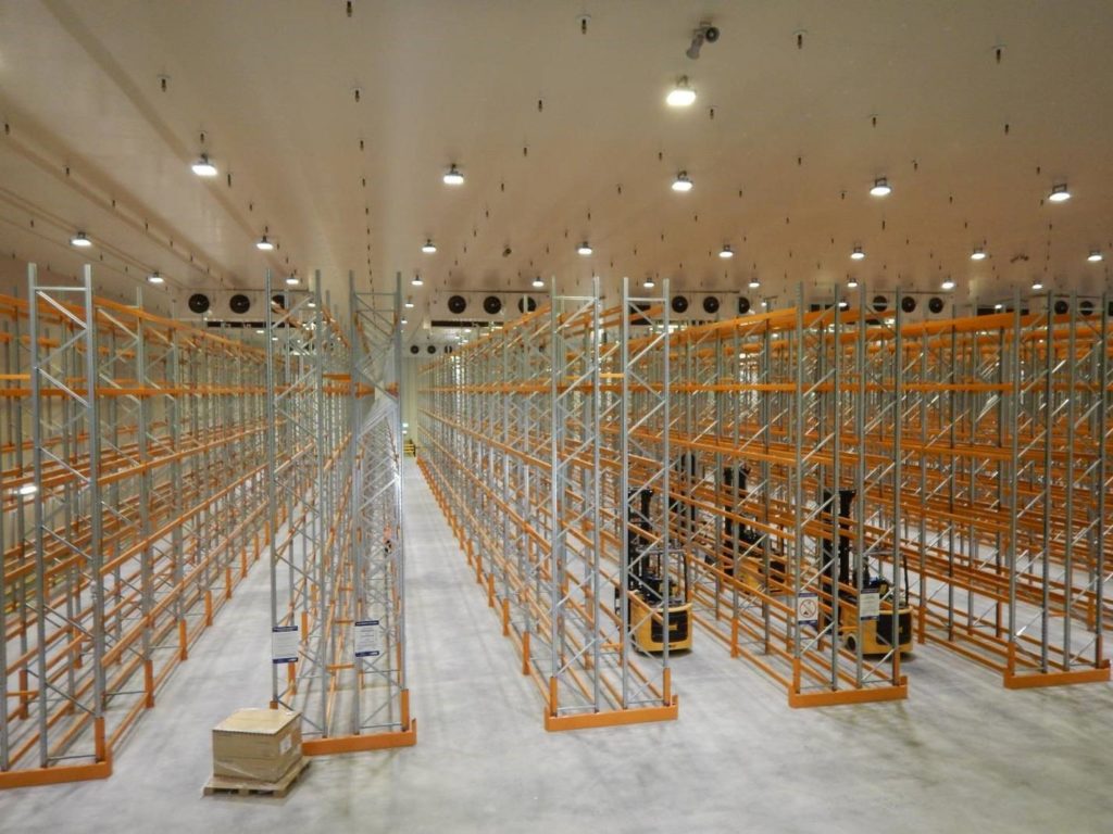
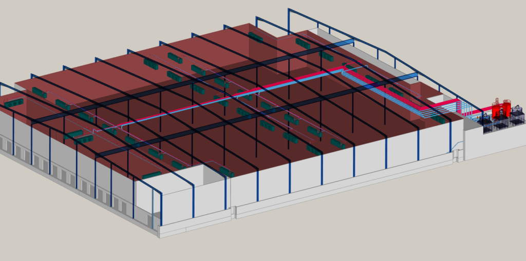
The single large cool room and loading dock are fitted with forty Guntner brand glycol to air heat exchangers arranged in four circuits of eight blowers for the main room and one circuit of eight
for the dock/Annex.
Piping is in 200mm diameter stainless steel tube, and to a lesser extent copper tube. The insulation is metal clad, and filled with 50 mm of expanding foam.
This arrangement allows the compressor packages to have the smallest possible ammonia charge, and also allows the individual systems to be removed from service for maintenance without affecting the overall site cooling.
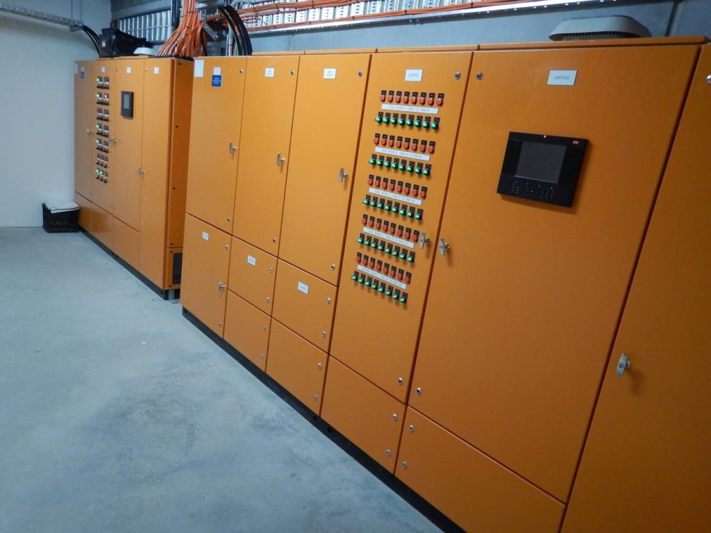
The compressors sets have local on board compressor management by a dedicated PLC control panel, while the site has a Danfoss control system that controls and monitors the pumps, blowers fans and so on, so real time control and monitoring is available both on and off site.
Detailed description
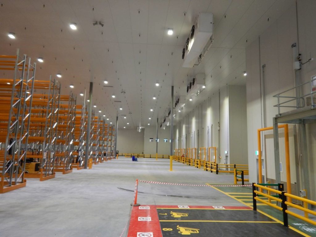
The cool room is approximately 90m x 90m x 10m high (7387m2 ) and holds 5646 pallets in the racking plus non racked storage.
The loading dock is approximately 15m x 90m x 10m high (982m2 )
Room temperature 2 to 4 deg C
Refrigerant R717 (AMMONIA) with propylene glycol as a secondary fluid
Screw compressor Mycom JL170 with economizer sub cooler and variable volume ratio valve
603 kw Q 132 kw Pe @ -7 sst & 35 sct
COP 4.58 : 1
Cooling tower Evapco MMT 110 900KW cooling capacity ( x 3 )
glycol coolers Guntner 45kw Q @ 3 deg C glycol – 4 in & 2 out ( x 40 )
The chiller packages
There are three identical chiller packages each of 607kw refrigeration capacity at -7deg c Saturated suction temperature / 35deg C saturated condensing temperature and 3300rpm with economizer liquid sub cooling.
The compressor packages are built by Mycom Australia and have a vertical oil separator ,
150kw 2pole motor , with direct drive coupling and self -aligning coupling housing , a water cooled oil cooler, oil pump and motor , and all the standard valves and controls to allow for normal operation and service.
An on board electrical control panel have a PLC to monitor and control the compressor package, and will control the compressor speed via a Danfoss Variable Speed drive , and also control the capacity regulation slide valve so that the best possible energy efficiency is maintained.
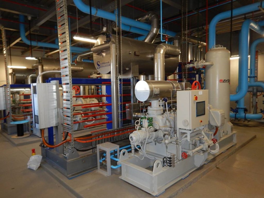
The condensers are a gasket type plate heat exchanger, and are fed with cooling water from a dedicated cooling tower located above the plant room.
The leaving liquid ammonia is sub cooled in a second plate heat exchanger economizer located below the condenser.
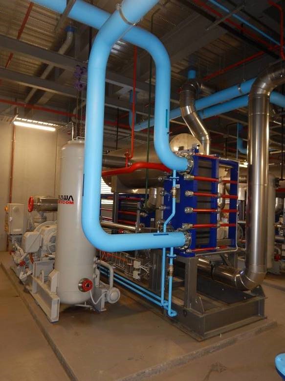
Sub cooled ammonia liquid is feed to a high side float which directs the ammonia to the low side accumulator vessel so a working level is maintained in the vessel.
Liquid ammonia from the accumulator is gravity feed into the plate heat exchanger evaporator, so that the glycol pumped through the evaporator is cooled. Vapor rising from the heat exchanger is drawn off the vessel and back to the compressor for recompression.
An oil drain is located on the supply Colum that feeds the evaporator, so oil can be removed from the system as required.
The accumulator vessel has a high level safety float switch, level sight glasses and all necessary valves and devices for normal operation and service.
The compressor and accumulator skids are located next to each other so that service can be undertaken without difficulty, and the refrigerant charge can be 160kg.
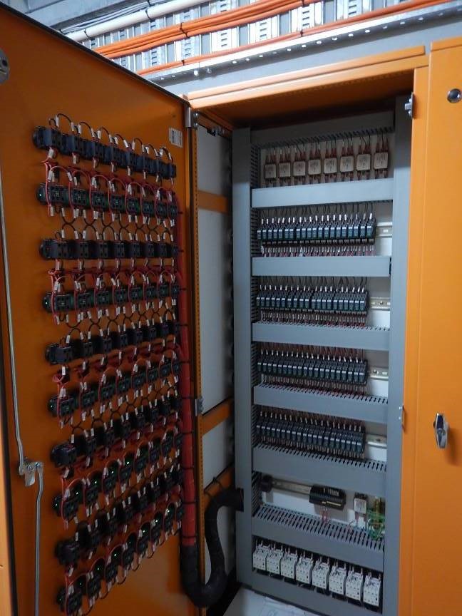
Each package has a dedicated electrical panel to provide the control and safety devices for that package.
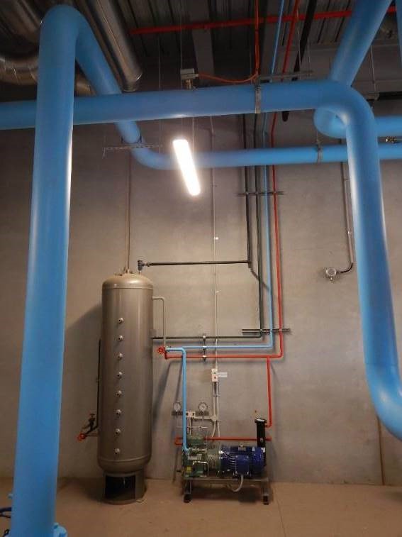
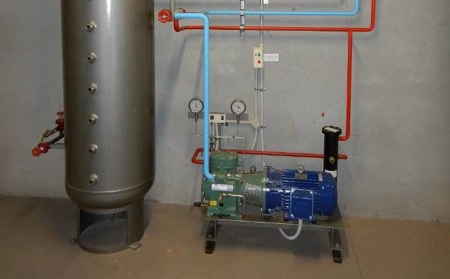
A permanent service receiver vessel is provided, and hard piped to three service lines (discharge, suction and liquid) that connect up to each of the packages, so that the refrigerant can be transferred from the packages to the receiver vessel and back again, so that servicing can be under taken.
A small Bitzer ammonia pump out compressor is also piped into the service system so that the packages can be fully pumped out, to reduce the amount of ammonia that can remain in a package during service .
The oil systems are also interconnected by service lines. The entire refrigerant charge of a system can be removed in 120 seconds should the need arise.
Suction, discharge Gas or liquid refrigerant can be transfused to and from the service receiver, or between chiller packages so maintenance can be undertaken in a safe and time efficient way.
The evaporative cooling towers
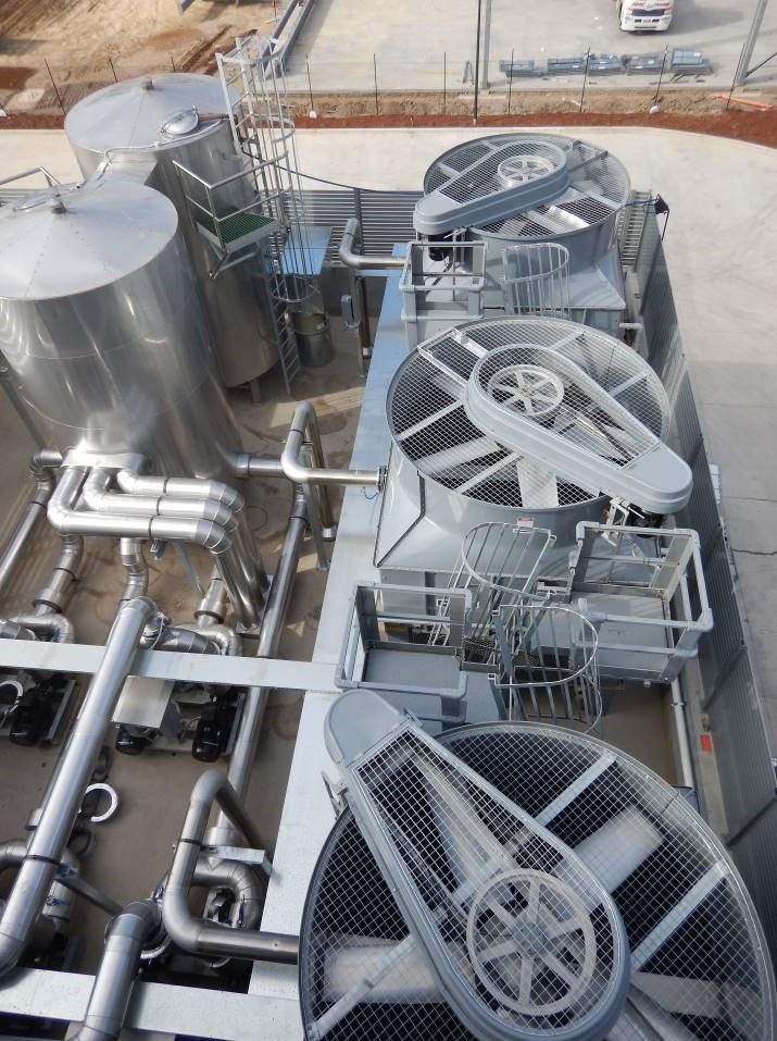
Three Evapco cooling towers are located above the compressor sets so that each compressor package is independently supplied with cooling water.
The towers are 900kw capacity which provides cooling water to the Alfa Laval plate condenser and oil cooler, and have a single fan controlled by VSD and a run and standby pump set each with VSD control are located in the plant room below the towers.
The 7.5kw fan is controlled so that the sump temperature of the tower is maintained at a constant temperature, and the pumps are controlled so that the condensing temperature is maintained in a tight operating zone.
The 900 kw capacity is engineered to allow for energy efficient operation under all conditions including start up under heavy load after a plant shut down.
The glycol tanks
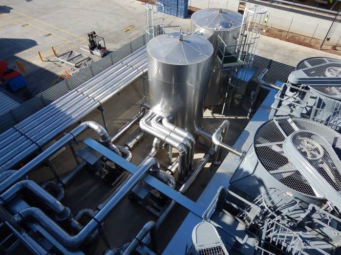
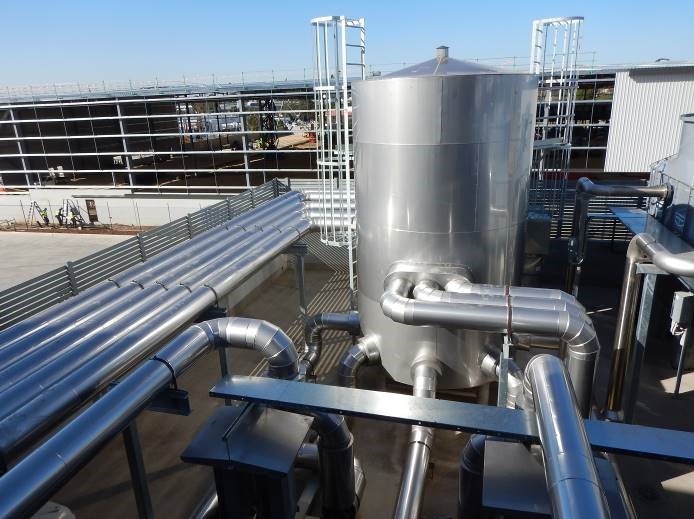
The two glycol tanks are each 2.4m diameter and 4 m high (plus the dished ends and legs) and have a storage capacity of 16000 L each.
The supply tank takes glycol from the chillers and store it ready to be delivered by the supply pumps to the cool room. Three 200mm supply pipes feed glycol from the chillers into the tank and 5 x 200mm pipes deliver the glycol to the pump sets.
2 x 16000 Litre stainless steel glycol tanks with spillway and s/steel cladding
The return tank takes the returning glycol from the cool room via 5 x 200mm return lines and store it , ready for the chillers to cool the glycol .
The two tanks are connected together by a high-level spillway so that a high level in either tank will overflow into the adjacent tank so that a loss of glycol is prevented.
The tanks are made of 316 grade stainless steel and insulated in 75mm of insulation and protected by a s/steel skin. Sensors are provided to shut the system down in the event of a glycol level fault, and the waste treatment plant is also controlled so that any significant loss of glycol will not be pumped to waste.
The pump sets
Each pump sets has a run /standby arrangement plus isolation valves, check valves , pressure gauges and pressure transducers , mounted on a common hot dip galvanized frame.
The pumps are Grunfoss brand and each pump has a dedicated Danfoss variable speed drive to maintain the pump discharge pressure at a constant delivery pressure.
The pump sets are piped in copper to the inlet and outlet flanges.
Pump sets run and standby Auto change over with VSD on all pumps
The glycol to air heat exchangers
Forty Guntner brand glycol to air heat exchangers (blowers) are arranged in 4 groups of 8 for the main room and one group of 8 for the loading dock.
Each blower takes glycol from the supply line at a rate of 5.7l/sec with an entry temperature of -4 deg C and a leaving temperature of -2 deg C. The air flow volume is 15.1m/s with a velocity of 2.6m/s and an air throw of 45m.
The blower have 3 fans and will absorb 2.7amps of power. The noise level will be 67db at 3m. The blowers are mounted to the ceiling and are approximately 8 m above the floor level.
An air on temperature sensor monitors the air in the room and whenever the air temperature is within 2 deg C of the set point the fans drop to low speed to conserve energy and reduce the sound level in the occupied space. If the air temperature rises above the 2 deg threshold the fans automatically switch to high speed to pull the temperature down rapidly before reverting to low speed.
Pipe design
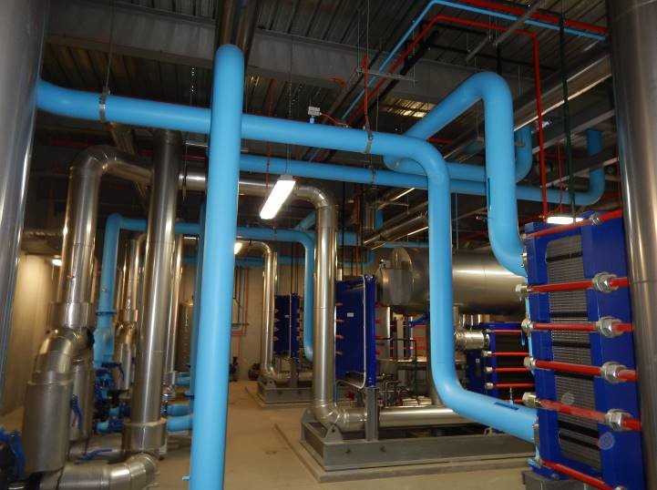
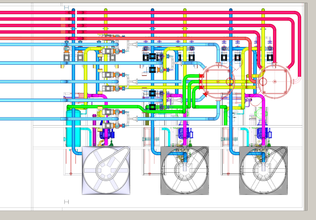
The majority of the pipe work is tig welded stainless steel tube. An orbital tig welder and pipe purge system was used to carry out the majority of the welding. The glycol pipes have a metal protective skin and 50mm of pumped expanding insulation. The main pipe runs leave the plant mezzanine deck at high level and pass through the centre of the ceiling space above the cool room.
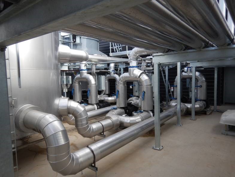
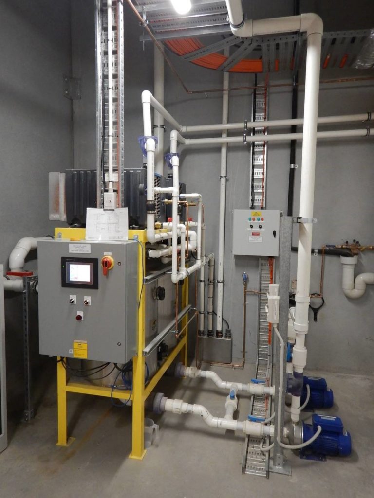
Glycol pipe work in the plant room
Each set of eight blowers has a 200mm supply and 200mm return line that each split into two to provide coolant to four blowers each side , stepping down in size at each Tee , so the flow velocity in the pipe run remains as constant as possible. The Tees are full size with reducers on the downstream side so that pressure drops are kept to a minimum. The final connection to the blowers will be 2-1/2” pipes run in copper tube, and will include a three way control valve to adjust the amount of cooling at each fixture. A 0 to 10 volt signal provided by an air on sensor will control the modulating valve so the cooling coil is increasingly bypassed as the air on temperature approaches the design condition. As room temperature reduces the glycol is diverted around the cooling coil which reduces the dropper drop in the pipe work and allows the delivery pump to slow down to further save energy.
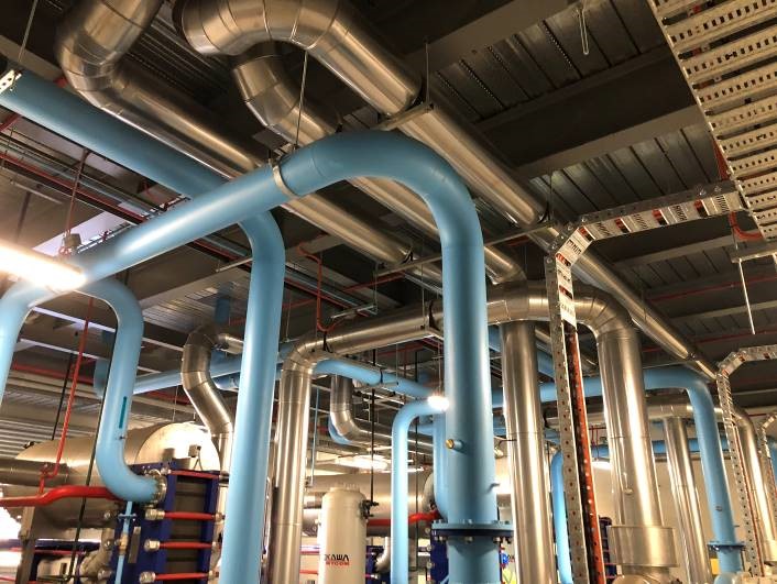
The pipe work for the glycol inside the plant room is also stainless steel with metal skin poured insulation, while the condenser water pipes are not insulated.
Plant room safety

The plant room is a restricted area, due to the nature of the refrigerant. Anhydrous Ammonia which is a Class B2 refrigerant which requires some special preparation in the plant area.
The room is fitted with a LEL (lower explosive limit) gas detection sensor which will shut down the electrical system, inside the room if the ammonia sensor measures a level of more than 1/3 of the lower explosive limit of ammonia in the air within the space. This shunt trip will remove power from all devices that are not wired and designed as flame proof.
The plant room exhaust fan, and the emergency lighting are flame proof type units.
A VSD driven supply and exhaust fans circulate the air within the plant room so that it remains within normal safe conditions for this type of application. The pump out system is a key safety feature as it allows all works on the ammonia packages to be done with all the refrigerant removed from the packages and held in safe storage within the plant room.
The entire ammonia charge never leaves the compressor room.
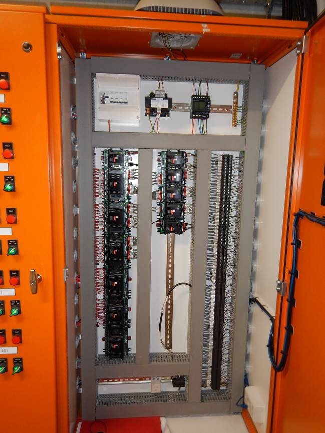
The electrical panels for the chillers are in a separate control room within the plant room so they are not in the same general space as the ammonia. This electrical room has a fire rated construction and the wall between the two has a flexi glass window so the plant can be observed from inside the electrical room. This allows the system to meet code, and greatly reduce the amount of equipment that is shunt trip protected. There are three compressor panels that each operate one chiller system. The compressor / condenser/ evaporator, cooling tower fans and pumps and the compressor VSD are controlled by this panel.
These three panels are located outside the main compressor room , in a small electrical room so an operator or service technician can observe the plant from the electrical room via a flexi glass window.
The main electrical distribution panel is located in the upstairs switch room above the plant room.
This panel supply’s the three chiller panels, plus it contains the control system for the site and the contactors and overloads etc for the glycol pumps which are all VSD controlled.
As major loads on this panel are all controlled by VSD this panels supply does not need to be supplied from the power factor correction panel as the VSD,s will supply corrected voltage to each device.
A second electrical panel also in the up stairs switch room controls the fan motors for the Guntner coolers and the plant room exhaust fans.
Electrical panels
The condensate drain system is a vacuum recovery system so that the drain lines from each of the forty blowers inside the refrigerated space are turned upwards into the ceiling space. This prevents damage from forklifts etc. The system requires significantly less drainage pipe work within the floor of the cool room and annex, so this additional cost could be removed from the plumbing package.
Water collected by the vacuum system is feed to the cooling towers to reduce water usage from the mains water supply.
The project builder was Taylor constructions and they entered the project into the “ Master builders association “ industry awards for 2018 in the $20 to $50 million commercial building category which they won.
The finish of the project is to the highest level, and the plant has been extremely reliable and generally doesn’t ever run more than one compressor set , which is in part due to the very high energy efficiency of the ammonia system and also a result of using floor insulation and very high spec ceiling and wall panels to keep the cold in.
All the doors have roll fast vinyl doors fitted to reduce air infiltration load, and every opportunity has been taken to use VSD’s and other advanced technologies to minimize the power consumption and make the building have as light a foot print as possible on the environment.
Lighting is by LED type fixtures with motion sensors to reduce the light power when it is appropriate to do so.
The site was fitted with a power quality meter for the first 12 months to establish that the supply was stable and to monitor the power consumption as a base line for future operation.

The graph above shows peak demand during the hottest days of summer with the plant outperforming our expectations by a considerable amount. Peak demand was 150 amps per phase, will average across this period of 116 amps and the twelve month average was 110 amps. The building is approximately 9450 m2 of floor area. the plant averaged 1 amp per phase per 85.9m2 over twelve months operation.
The building was registered under the green start rating programme and features such as the environmentally friendly refrigerants used and the Vacuum drain system recovering water for use in the cooling towers assisted greatly in the building high performance.

Summary
An enormous amount of engineering and planning went into the design of the project so that the system would deliver best in class performance.
Every item installed was engineered to provide the best possible performance while maintaining outstanding reliability and the highest level of site safety.
The energy saving features that were demanded by the owner were expanded on by the design team to deliver a project that has combined the latest technology available to re-invent what a large scale cold storage facility should look like in the year 2020.


